


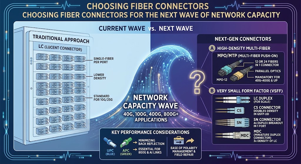
Network capacity is advancing rapidly: 400G and 800G systems are already in use, while 1.6 Tb/s platforms are on the roadmap. This progression reflects growing demand from artificial intelligence computing, high-performance computing, cloud services, and hyperscale facilities. These environments move larger volumes of data and connect more processors, storage systems, and network devices, increasing both bandwidth requirements and the number of optical ports needed. As a result, connector selection is no longer a minor cabling detail. It can affect how efficiently a network expands, how reliably it operates, and how readily it can adopt faster generations of equipment.
LC duplex connectors remain widely deployed because their compact size, dependable performance, and broad compatibility make them a practical choice across many established systems. Their familiar interfaces can simplify maintenance and help organizations work with existing transceivers and cabling. However, higher port density can make panel space increasingly valuable. Very small form factor (VSFF) connectors, including SN, CS, and MDC designs, address this constraint. With 1.25 mm ferrules, these options can accommodate more connections within limited space, supporting denser installations and offering potential alternatives to LC in selected applications.
Greater density alone does not determine the right choice. A new connector form factor must fit the project’s transceivers, patch panels, cabling practices, testing procedures, and maintenance capabilities. Organizations should also consider the installed base: replacing established LC infrastructure can involve transition costs, staff training, and coordination across equipment generations. A practical migration path may include using VSFF connectors in new, space-constrained deployments while maintaining LC where compatibility or operational continuity is important. Evaluating these factors early helps prevent short-term density gains from creating avoidable integration challenges. Connector decisions should therefore form part of capacity planning, aligning present requirements with a network’s expected growth, reliability needs, and future upgrades.
MPO and MTP connectors have long served as established choices for multi-fiber arrays, allowing many optical fibers to connect through a compact interface. They support high-density cabling in data centers and have helped simplify links between switches, panels, and other network equipment. However, the scale and architecture of new deployments are changing capacity requirements. AI training clusters, GPU fabrics, and hyperscale cloud environments can demand substantially more parallel optical connections, including at active equipment and patch panels where space is limited.
To accommodate that growth, designers are considering very small form factor (VSFF) multi-fiber connectors, including MMC and SN-MT. These options can fit more fiber connections into a given area, potentially increasing density at the front of switches and within cross-connect fields. Connector selection is therefore a consequential design decision, not simply a matter of choosing a cable interface. It can affect equipment layout, migration paths, service access, and the ability to scale bandwidth as GPU clusters and cloud networks expand.
Higher density also brings an operational trade-off. More ports and more mating cycles create additional opportunities for dust or other contamination to reach connector end faces. Even small particles can disrupt optical transmission, contributing to elevated loss, errors, or intermittent performance. Lens-based designs, including MXC and EBO MPE, as well as newer multi-fiber lens connectors, can be less sensitive to dirt because their optical interfaces do not rely on exposed fiber cores in the same way as conventional physical-contact designs. This does not remove the need for inspection and sound handling practices, but it may reduce the impact of contamination and the frequency of cleaning. In large installations, where thousands of connections must operate dependably, that tolerance can ease maintenance demands and support consistent service. Evaluating density alongside cleanliness, serviceability, and reliability helps teams select connectors suited to the demands of next-generation networks.
Every optical transmission standard specifies a maximum channel attenuation that equipment can tolerate while maintaining reliable operation. The channel’s total loss is not determined by fiber alone: it includes attenuation along the fiber, losses at connector pairs, and losses at splices. Each component consumes part of the standard’s available loss budget. A design should therefore begin with the complete end-to-end path, including its planned length, connection points, splices, and operating margin, rather than considering the connector as an isolated component.
As the number of connection points increases, less of the total allowance remains for each individual connector. For example, a link with several patch panels and equipment interfaces may contain many mated connector pairs; even modest loss at each point can accumulate into a substantial share of the channel budget. Designers should calculate expected loss across all elements and allow for manufacturing variation, installation conditions, and future maintenance. Connector performance should be evaluated in the context of this full channel architecture, not selected solely by comparing a single insertion-loss figure on a datasheet. A component that meets a standalone specification may still be unsuitable if the overall link has little remaining margin.
Higher data rates and the adoption of PAM4 modulation also increase the importance of managing optical reflections. Reflected light can interfere with the transmitted signal, making return loss an important qualification measure alongside insertion loss. APC, or angled physical contact, polishing creates an approximately 8-degree angle on the connector end face. This geometry directs reflected light away from the fiber core and helps reduce back reflections. APC connectors are consequently gaining a larger role in high-speed links and multi-fiber systems, where signal integrity and dense interconnection both matter. When choosing and qualifying connectors, verify that insertion-loss and return-loss requirements are met across the intended channel, including all mated interfaces. Reviewing test methods, connector compatibility, and expected field conditions helps confirm that the selected solution will support the system’s performance targets, rather than merely satisfying an isolated component specification.
Connector selection is not determined by physical fit alone. Industry standards and network specifications define which interfaces are permitted in particular equipment and network segments, helping maintain interoperability, optical performance, and predictable installation practices. A connector that can be adapted to a port may still be unsuitable if it does not meet the governing requirements for that location. Operators should therefore identify the applicable standards, equipment specifications, and segment-level rules before evaluating new designs.
These requirements can be specific. LC interfaces are required for certain device connections, while MPO interfaces are defined for multi-fiber applications, including systems that need to connect several fibers through a compact interface. In network access areas, requirements may be especially strict because performance at the customer or distribution boundary affects service quality. For example, a single-mode connection may need to satisfy a defined return-loss limit. Connector geometry, polish, mating compatibility, and installation condition can all influence whether that limit is achieved in practice.
An innovative connector is not automatically suitable for every part of a network. A design that offers higher density or simpler handling may be appropriate in one segment but disallowed in another by interface rules, equipment requirements, or performance thresholds. Deployment teams should verify that the connector is explicitly permitted for its intended role rather than relying on adapters or assumptions about compatibility. This check should include both the connector standard and the requirements of the specific application.
As capacity needs grow, operators can assess new options against a balanced set of considerations: density, optical performance, cleanliness, compatibility with installed equipment, and practical migration plans. A high-density solution may reduce space demands, but it must also support reliable inspection and cleaning and fit the network’s maintenance processes. Migration planning should account for cabling, test methods, spares, and future interoperability. Confirming that each chosen solution is allowed in its intended segment helps ensure that design gains do not come at the expense of compliance or operational reliability.